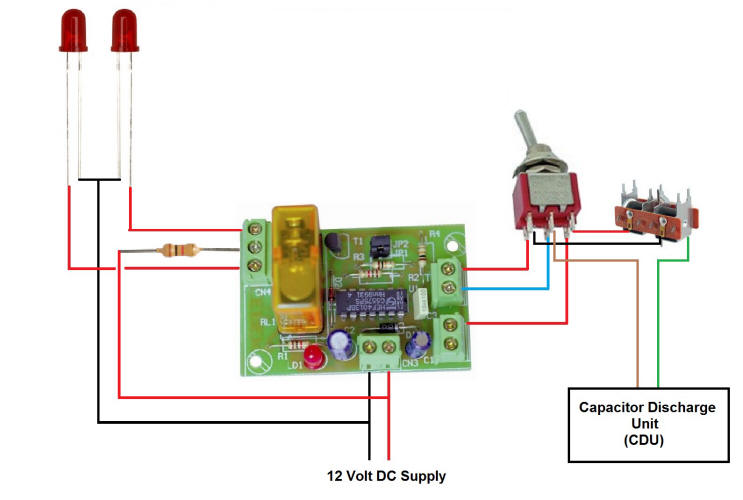
Latching Relay to give LED Indication and Operate Point Motor
Using our Latching Relay module our example will show you how to connect a Double Pole c/off Biased Toggle Switch (On) off (On) to control a couple of LED's to indicate position of your Point Motor.
(Figure 1) Shows the relay connected to a separate 12 Volt DC supply. We have connected the positive (Red Wire) to the common (COM) terminal on the relay via a suitable load resistor*. The Normally Closed terminal (NC) is wired to one LED and the Normally Open terminal (NO) is wired to the other LED.The negative side of both LED's are connected to the power supply (Black Wire). When the toggle switch is moved from its centre (off) position the contacts will close and activate the relay or de-activate it depending on its last operation. At the same time the other half of the Double pole switch is connected to your point motor as indicated by the Red and Black wires, the Capacitor Discharge Unit (CDU) is connected to the Switch and Motor by the Brown and Green wires.
Alternatively the DPDT switch could be substituted for two momentary push button switches (212-46*) or two illuminated push switches (212-77*)
Parts List: 1 x Cebek Latching Relay Module Order Code I-9 1 x DPDT c/off Biased Switch Order Code 218-223 * Load Resistor 1K ¼ Watt is suitable when using LED's on a 12 Volt DC Supply Order Code 906-210e
If you follow this advice you should have no problem switching on and off any device connected to the relay.
See our full range of Electronic Modules |  Figure 1 |
ESR Electronic Components Ltd Cullercoats Tyne and Wear NE30 4PQ