
Microphone Characteristics
There are many types of microphone on the market today, this is because there are so many types of sounds. Vocals, electric guitar, clarinet, drums, keyboards, violins etc all of which generate different frequencies or combinations of frequencies. The major differences between microphones are the transducer type and the pickup pattern. The pickup pattern is the area around the microphone transducer where the sound is actually "heard" by the microphone.
Pickup Patterns
| Omni directional microphones (omni means "all" or "every") are equally sensitive to sound from all sides, picking up sound from every direction. The sound is very general and unfocused, if you are trying to capture sound from a particular subject or area it is likely to be overwhelmed by other noise. Omni directional microphones are good for ambient sound and group vocals. | 
Omni directional Polar Pattern |
| Cardioid microphones (unidirectional) are sensitive to sound only in a specific direction. The most common type features a cardioid (heart-shaped) pattern that rejects sound coming from behind the microphone. Sound is picked up mostly from the front, but to a lesser extent from the sides, emphasising the sound from which the microphone is pointed. Cardioid microphones are a very versatile microphone, ideal for general handheld applications. | 
Cardioid Polar Pattern |
| Hypercardioid microphones are an exaggerated version of the cardioid pattern. It is very directional and eliminates most sound from the sides and rear. Due to the long thin design of hypercardioid microphones, they are often referred to as shotgun or rifle mikes. These microphones can be very useful for isolating the sound from a subject or direction when there is a lot of ambient noise. They can also be used to pick up sound from a subject at a distance. | 
Hypercardioid Polar Pattern |
Transducer Types
There are two basic microphone transducers, condenser and dynamic. To understand the difference between these types of microphones, you have to know something about how they work.
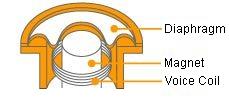
Dynamic Microphone Transducer | In a dynamic microphone a coil of wire is mounted on a diaphragm, which sits inside a magnetic field. When the diaphragm is moved by the sound source the resulting fluctuations in the magnetic field create an electric current that travels from the microphone to the mixer or amplifier. Dynamic microphones are rugged and can handle high sound pressure levels, like those delivered by kick drums, snare drums, and aggressive vocals. |
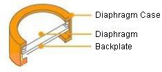
Condenser Microphone Transducer | A condenser microphone requires a constant electric charge, provided by a battery or phantom power from your mixer. The condenser diaphragm has less mass, which requires less energy to move, so condenser microphones are more sensitive than dynamic microphones. These microphones are very responsive to high frequencies produced by an acoustic guitars or cymbals on a drum-kit and are used extensively in broadcast, recording and sound reinforcement. |
Impedance
Impedance is an electronic term which measures the amount of opposition a device has to an AC current. It is the combined effect of capacitance, inductance, and resistance on a signal. It is measured in ohms and shown with the Greek omega symbol Ω. All microphones have a rated impedance, this may be written on the microphone itself or on the specification sheet provided with the microphone. There are two general classifications for microphone impedance.
| Low Impedance | 200 - 1000 Ω |
| High Impedance | 10,000 - 50,000Ω |
The preferred choice of microphone impedance should always be low (600Ω). A low impedance microphone should generally be connected to an input with the same or higher impedance. If a microphone is connected to an input with lower impedance, there will be a reduction in signal strength.
Frequency Response
The Frequency response curve refers to the way a microphone responds to different frequencies. It is a characteristic of all microphones that some frequencies are exaggerated and others are attenuated. A frequency response which favours higher frequencies means that the resulting audio output will have more treble than the original sound.
The graph above shows a typical response curve for a microphone. An ideal "flat" frequency response means that the microphone is equally sensitive to all frequencies, so no frequencies would be exaggerated or reduced resulting in a more accurate representation of the original sound. In the real world a perfectly flat response is not possible and in many cases a tailored frequency response is more useful. When selecting a microphone, the frequency response curve will give some indication as to how the microphone will respond at different frequencies
Balanced Output
The term balanced line means the shield of the cable is connected to ground and the audio signals flow in two conductors which are not connected to ground. Fig a) The signal currents are flowing in opposite directions at any given moment in the pair of wires so any electrical noise is common to both wires, and so is effectively cancelled out.

Fig a
Most modern microphones have balanced outputs and this offers real advantages over unbalanced microphones. Balanced lines are much less susceptible to radio frequency interference (RFI) and the pickup of the other electrical generated noise.
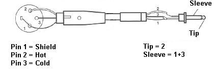
Fig b
With an unbalanced signal, the cancellation effect can not happen when only one signal wire plus the shield is used. It is possible to wire a low-impedance microphone directly to an unbalanced low-impedance input. (Fig b) but the noise-cancelling benefit will be lost. This should not be a problem with cable runs of about 6M, but if longer cables are used, a balanced input is preferred.
Phantom Power
Phantom power is a method for supplying voltage to a device, using it's signal cable. It is often used to supply condenser type microphones with the required polarizing voltage and power for any built-in preamplifiers.
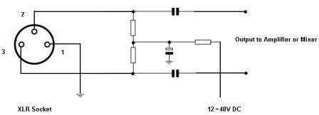
Fig c
Phantom powering consists of a voltage being applied equally through the hot and cold signals lines of a balanced microphone connector. The supply voltage (12-48V) is with reference to the ground pin or shield of the connector. Fig c shows how the voltage is applied to the microphone. Phantom power supplies are often built into mixing desks, amplifiers or other equipment that takes a signal direct from a microphone.
Radio Microphones
Home
ESR Electronic Components Ltd Cullercoats Tyne and Wear NE30 4PQ