|
Solenoid point motors work by briefly energising a coil which pulls an internal slug to throw the points. Without a CDU, the point motor relies directly on the capacity of your layout power supply to energise the coils. This can cause several problems — especially on larger layouts or when more than one point is switched at once. |
|||
|
The LTS CPMI is very reliable and gives a strong switching action. It charges a capacitor slowly from your existing supply and, when a point is fired, discharges all stored energy in one firm, controlled pulse. This provides a consistent and positive throw every time and reduces the chance of partial throws. The energy is delivered in a short burst rather than continuous current. This protects your solenoid from the risk of overheating or burning out — even if a switch is held down or contacts stick |
|||
|
The module is fitted with a double pole, dual coil latching relay which operates every time the point motor is activated. One half of the relay contacts are configured to illuminate one of the two LED’s to give you a visual indication of the direction of the point. The other half (Aux Contact) can be used for a number of applications. |
|||
|
|
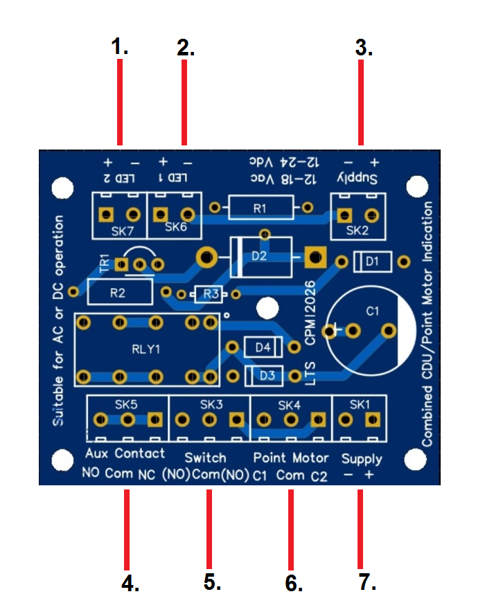
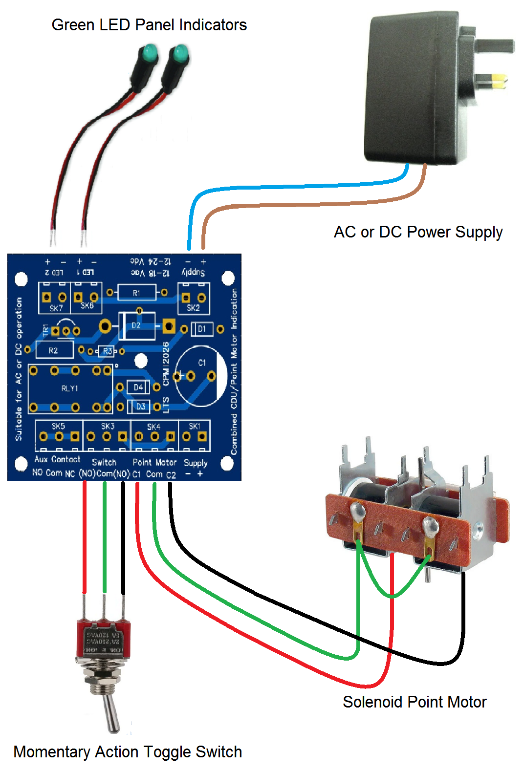
1/ LED 1. 2/ LED 2. 3/ Power Supply. 4/ Auxiliary Contacts. 5 Switch to activate point. 6/ Point Motor. 7 /Power Supply. |
||
|
The LTS CPMI operates from a 12 – 18 V AC (Typically 16 Volts AC) or from a 12 – 24 V DC source. The ‘Supply’ is connected to either 3. or 7.). The other then becomes an output to supply further modules. Connect the point motor leads to (6). Point motor coils are connected to (Coil 1) to C1 and Common and (Coil 2) C 2 and Common. Install your chosen switch in to your control panel and wire to terminals marked (5). The three wires coming from your switch are connected to the terminals marked (ON) Common (ON). Mount the LED’s on your control panel; they push through an 8.0mm hole from the front. Run the leads (355mm) from the LED’s to the terminals marked LED (1) and LED (2). These leads can cut or extended if required. (Watch polarity Red +, Black -). |
|||
 |
 |
 |
|
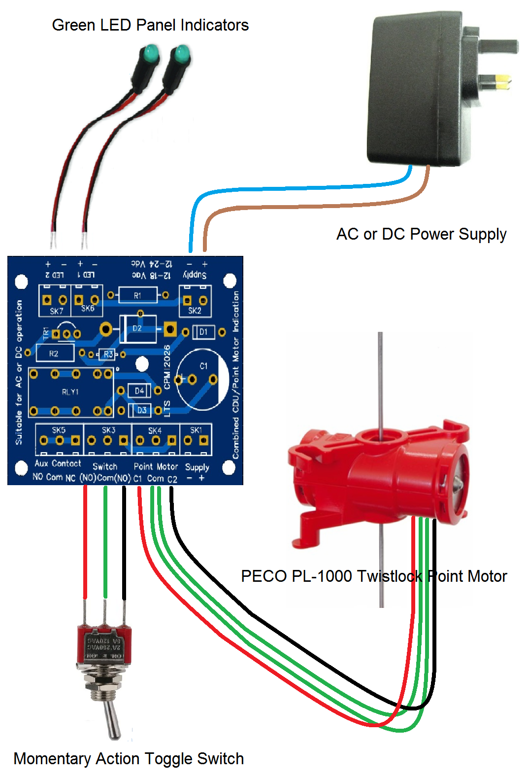
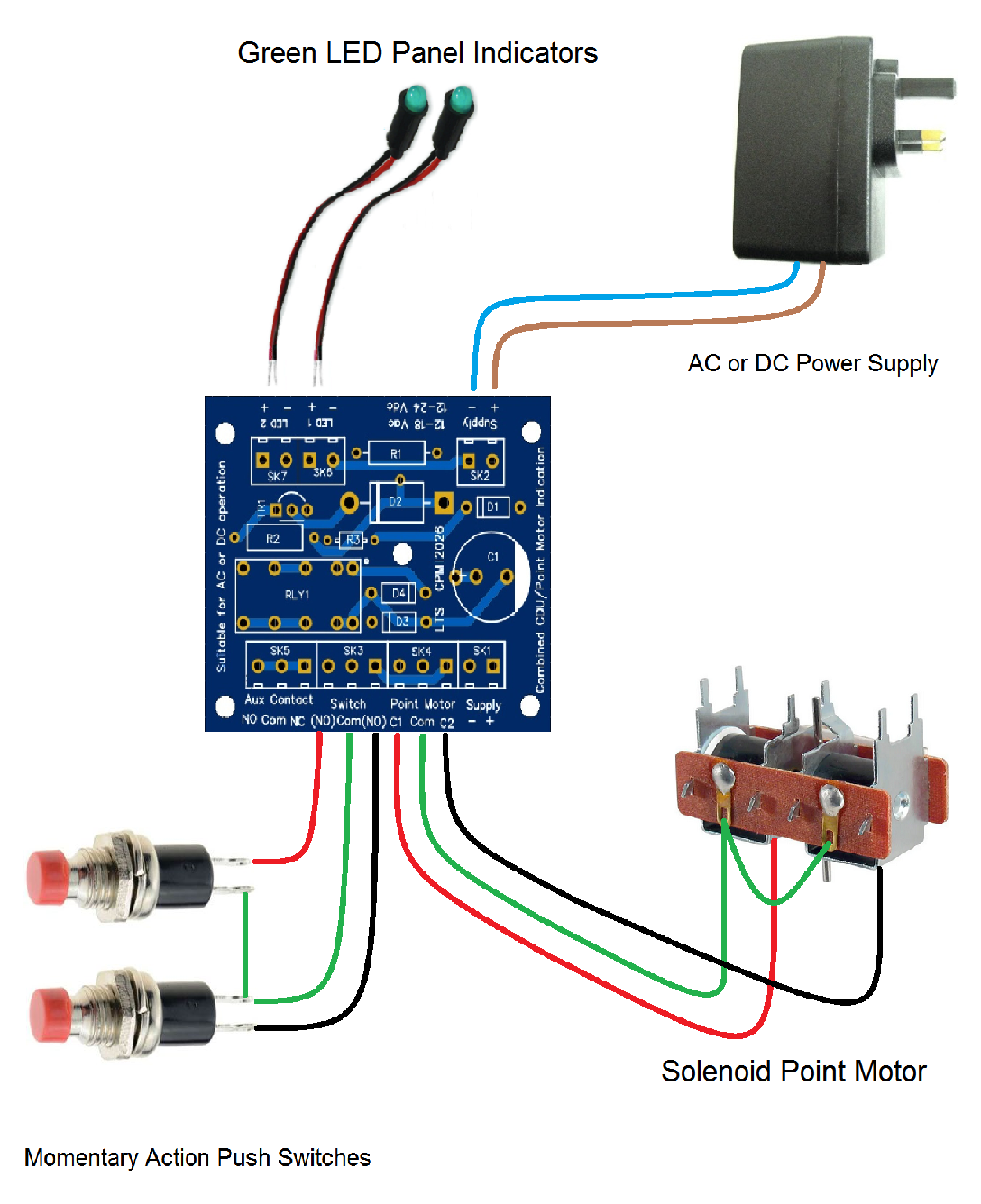
| Using a standard miniature toggle switch which is sprung loaded to return to the ‘off’ position. This is often described as (on) –off- (on) type of switch. It is shown wired to the classic type of solenoid point motor and to a PECO PL-1000 motor. Another popular method to activate your point motor is by using two momentary (Return to off when released) action push switches, these are connected as shown. | |||
|
LTS CPMI module is designed to be used with single track turnout fitted with solenoid point motor. The Capacitor Discharge Unit has the capacity to activate two point motors simultaneously when used in layouts that require two points to operate together. Two or more of these units can also be activated from a single switch making it ideal for matrix track switching options. The module has screw terminals for all connections there is no soldering required. |
|||
|
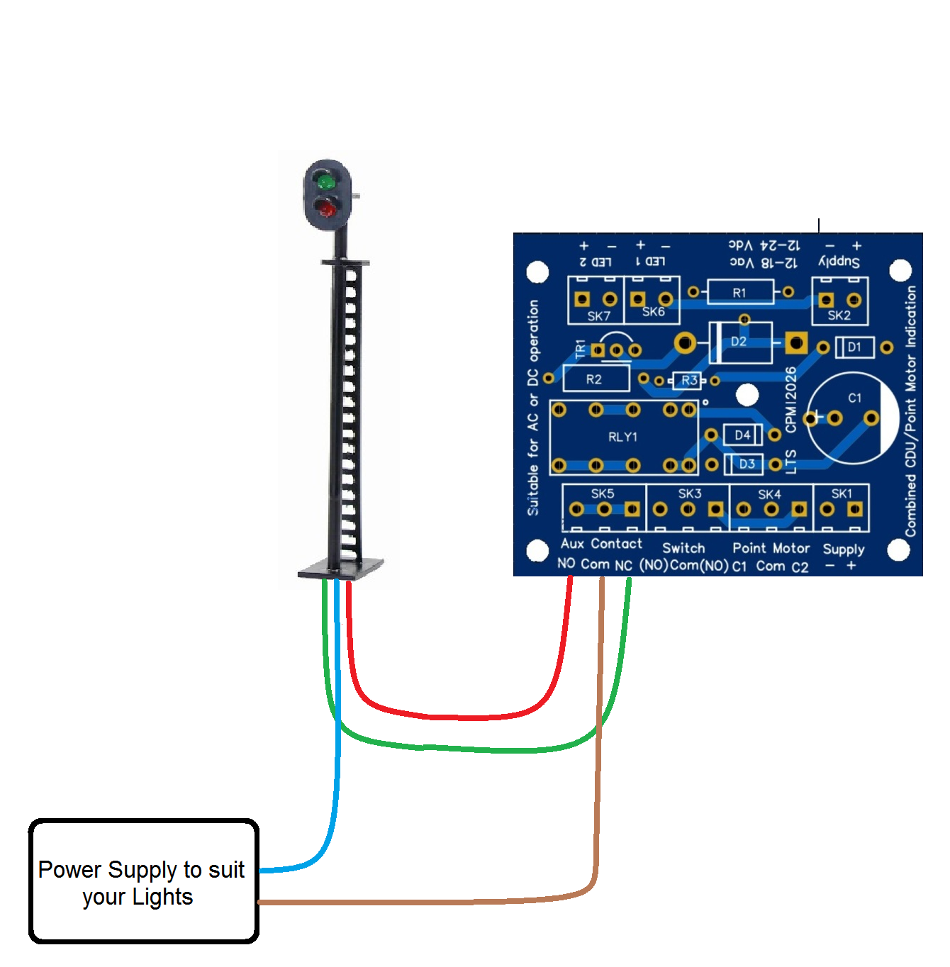
Auxiliary Contacts. The auxiliary contacts can be used for various switching application, shown below are some examples. Example 1. |
|||
|
|
If your layout has line side signalling the LTS CPMI can be used to change the colour of the lights. | ||
|
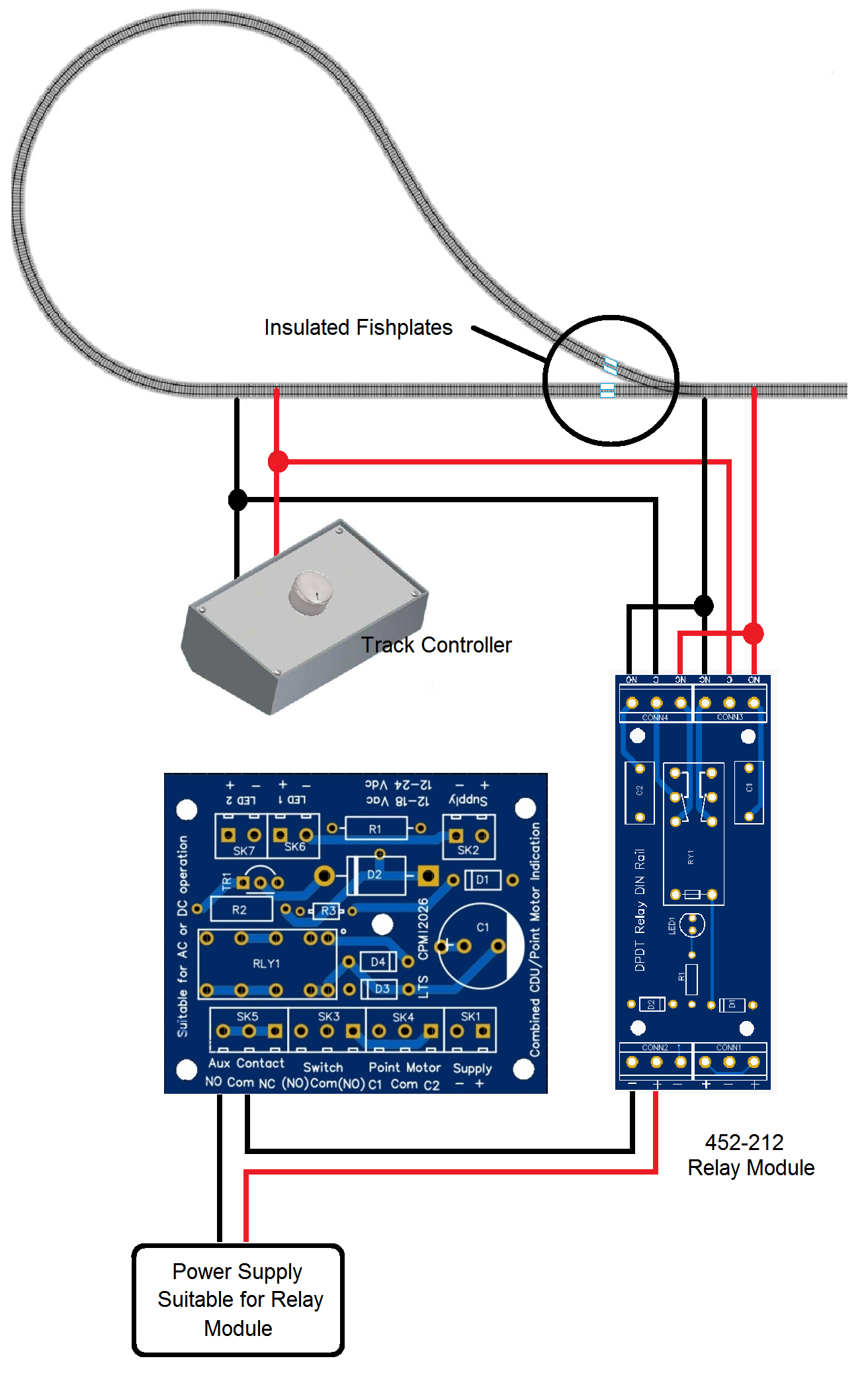
Example 2.
|
Another use of the auxiliary contacts is to control the polarity of the track if you have reversing loop incorporated in your layout. | ||
|
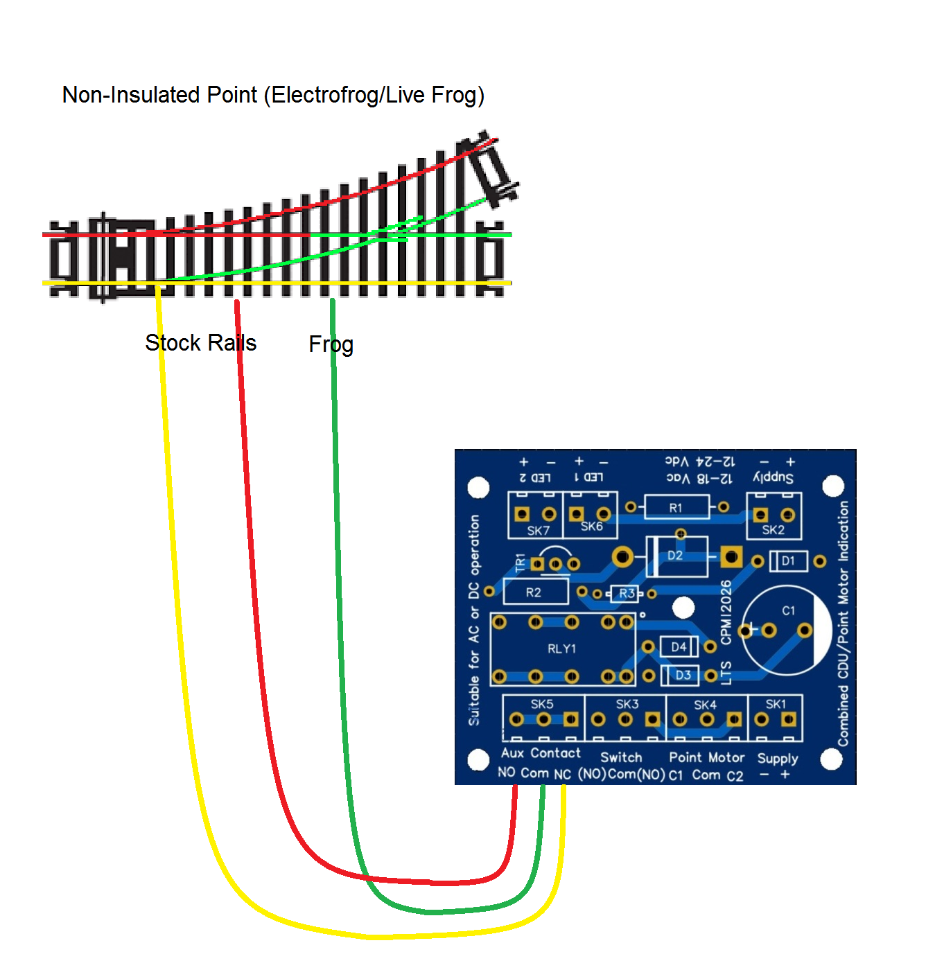
Example 3.
|
If you are using electrofrog points on your layout the auxiliary contacts can be connected as shown to change the polarity of the frog as the direction of the point is changed. | ||
|
The LTS CPMI is safe and low in maintenance, it is a solid-state device with no moving parts and requires no routine maintenance once installed.
SSP £19.45 |
|||
|
The copyright of this product is owned by Logistic Technical Services. All worldwide rights reserved. No part of this manual may be copied, reproduced, translated or reduced to any electronic medium or otherwise without the prior written consent of the copyright holder |
|||